Image

![]()
Now available as a fully searchable PDF collection – the Linear Audio USB stick!
See this page for details and ordering info.
Update Feb 2021: The latest version, V5, is now available in the diyaudio store. See the listing for the BOM, Assembly Guide and all other information.

My friend Patrick (EUVL) has discovered that when the regulator is switched on without load, there is a chance that the opamp non-inverting input is driven outside its limits. The way to prevent that is to replace zener diode D7 (see schematic) by two reverse-parallel small signal diodes, preferable Schottky. The two diodes, reverse-paralleled, should take the place of the D7 zenerdiode, as follows:
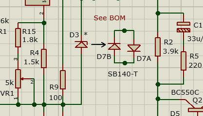
Previously I suggested BAT42 diodes here, but I now recommend SB140-T Schottky diodes, Mouser 621-SB140-T. There should be no problem to put them both on the current PCB but I will adapt the next version of the board for proper layout.
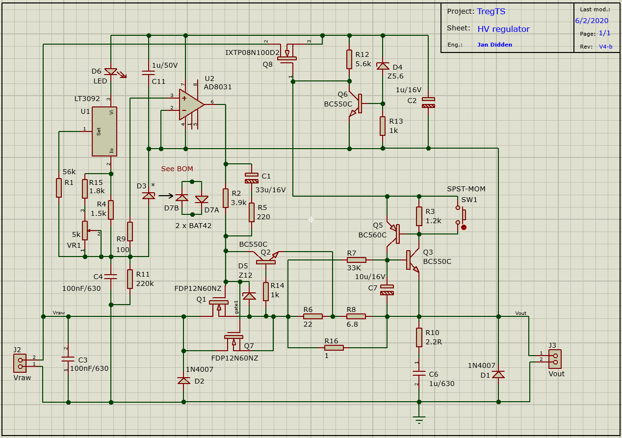
I have updated the schematic of the V4-b version of the last batch of boards, so that you can set the current limit with a single resistor rather than having to set two values. There is a new resistor R16, which you set for the current limit. Select it such that at your desired current limit, the voltage across R16 is about 0.6V. As shown, 1R, the limit is approximately 600mA. Resistors R6 (22R) and R8 (6.8R) are now fixed. I have also updated the other files (Stuffing Guide, Schematic, BOM) to version 4-b.
I have also noted an alternate for Q8, namely IXTP08N100D2. That will help with availability, so if you order kits from me, they can either come with an IXTP01N100D or an IXTP08N100D2.
I have received several questions for a version of the regulator that can handle more than 600V max. The issue here is the voltage handling capacity of the pass device Q1 MOSFET, and the capacitors C3, C4 and C6. Q8 is rated for 1kV so there's some leeway there. The problem with finding a higher-voltage Q1 is the SOA (Safe Operating Area). In case of short circuit, the full input voltage is across Q1 with the current at maximum. The used device can handle 600V at 400mA. The FCP850N80Z can handle 800V and has a reasonale SOA, max. 200mA. So if you set the current limit to 200mA max, this setup would be good up to 800V. You can replace C3 and C4 with 0.03uF/800V, mouser part number 667-ECW-H8303JV. They should fit the PCB. Unfortunately I could not find a drop-in replacement for C6 that could handle 800V. Mouser part # 871-B32774P8105K000 is an 840V box film cap with a pin pitch of 27.5mm. This will not fit the PCB directly but you may be able to jury-rig something up, for instance mounting it on the bottom side. Hope this is useful but note I have not tested this! If you do go this route, I'd like to hear from you, how it worked out.
Update 4 Nov 2019: Some time ago someone wondered what would happen if you connected the output to a fully charged capacitor while the input was off. It's not clear to me how that could happen; where you'd get a fully charged cap unless you have the regulator on. But this is easy to simulate so I did that. What happens is that the fully charged output cap discharges via the pass device parallel diode, which is normally off. I see a current of some 8uA flowing through the opamp inputs into the reference cap. In that scenario the max allowed voltage difference between the opamp inputs is exceeded. Why there is only 8uA is probably because the opamp model doesn't fully model the input stage over-voltage. I made a quick fix to replace D3 with a 2.7V zener diode. That keeps the opamp input stage voltage below some 2.5V, no problem. I just tried it out on my prototype and I see no difference in performance. So, if you are worried about that extremely unlikely scenario, put in a 2.7V zener at D3 and relax. Mouser 625-BZX85C2V7-TAP is a good one.
Full schematic V4-b PCB Stuffing Guide V4-b
Bill of Materials V4-b PDF How to set V4-b Vout and Ilim
Update 2 Nov 2017: AudioXpress has placed my AX T-Reg article online. Thank you Editor-in-Chief João Martins!
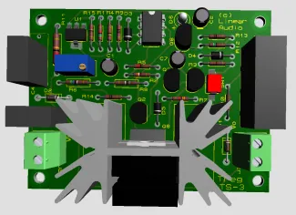
This is a project for a high-voltage regulator for tube amplifiers. The design will provide anything from 50V to 500V DC and more at up to 1A DC. The tube on the assembly in the picture is an EL84 for the preamp 50mA max version. The large 6528 plug-in will provide up to 500mA. The MOSFET regulator plug-in can handle up to 1A output current.
Measurements show low output impedance of less than 100mOhms, and hum and noise below 300uV, all over the audio bandwidth. Not bad for a tube supply, and no opamps!
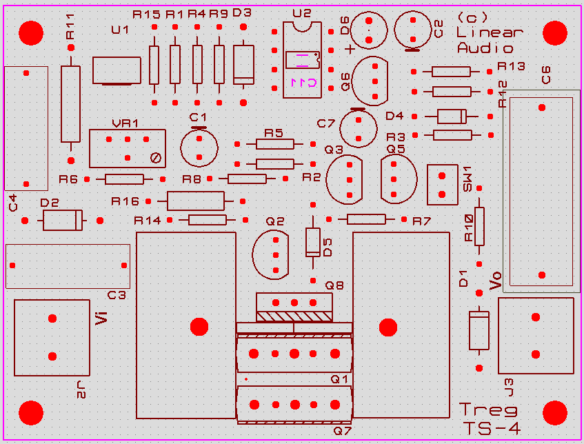
Update November 2016: I have updated the article but it has not been published. Several people asked me about a PCB for the updated design, but only a few have been produced. To accomodate interest, I have decided to publish the article and the PCB Gerber files here so people can have their own PCB manufactured and/or organise a Group Buy at diyaudio. Here's a color rendition of the layout showing a few SMDcaps at the solder side.
Of interest: I received a message from Jacques Dehaye from France, with a link to "The American Electricians Handbook". This book has a Motorola app note for an MC1466L and its cousin, the MC1566L.This is a clear diagram explaining the operation of the floating regulator. Thank you Jacques!
Also, John Walton alerted me that resistors R3 and R5 should be able to handle high voltage, up to 500V. These are available from the usual sources like Farnell and RS Components, from Multicomp and Vishay. Alternatively, you could make up R3 and R5 from two resistors in series of half the total value.
Stop press! There is an error on the DN2540 plug-in board available through Elektor. One end of R3 is going nowhere - this should be connected to K2. My apologies, it is entirely my fault. Thanks John Lopez!
As noted, the T-reg is based on the MC1466L floating voltage/current reg chip, now obsolete. Interestingly, Gary Lecomte has developed a discrete version (pcb actually) of that MC1466L! (Thanks John O'Neill).
One builder of the DN2540 version of T-reg had some problems with it and I discovered that it probably is related to (re)connecting a capacitive load with the regulator live. The pass device DN2540 has a max Id of only 500mA, which is sufficient for normal use but may be exceeded in some cases when (re)connecting a cap load.
Elektor have published the design in the March 2009 issues of the NL and UK magazines. AudioXpress has published an adapted version in their April 2009 issue.
The T-reg Stuffing Guides in the AX-article didn't come out very well so here are alternatives: Main board, 6080 board, EL84 board, DN2450 board.Boards for the original design may be obtained from Elektor through their PCB service - I have no more PCBs for this project available.
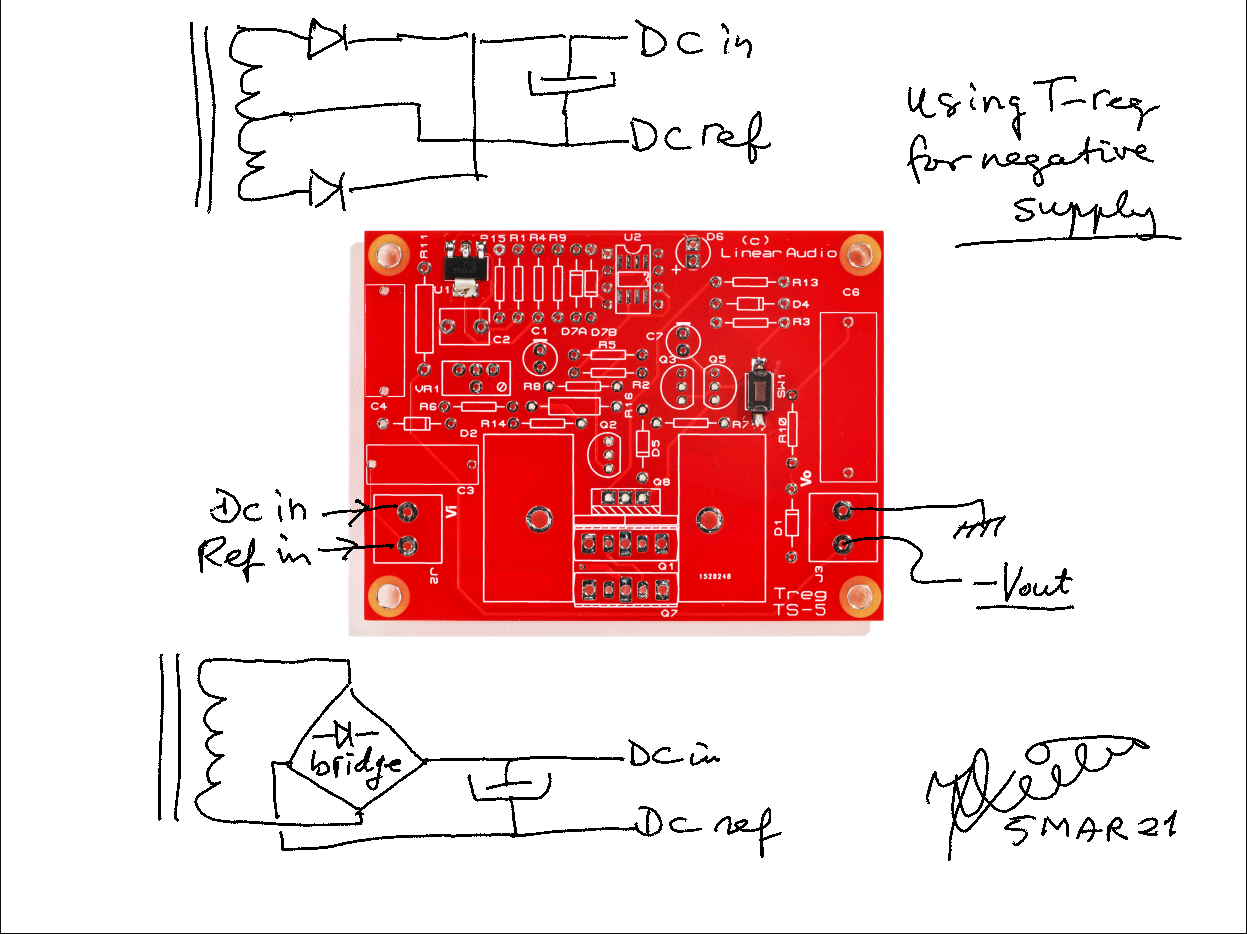
Update May 2012: I have redesigned this regulator as a stand-alone board with only the regulator, no rectifier, no time delay. You input the raw rectified DC and a supply voltage for the control circuit, and out comes the regulated voltage. Also redesigned the unit for a 'regular' enhancement mode MOSFET, tested with an IRF740. Works well, almost unlimited current capability, with substantial the same specs as the old unit, with less mains breakthrough. Can be 'hot plugged' into a load with no problems.
Update February 2013: I have submitted a follow-up article to Elektor, describing the new version which uses 'regular' power MOSFETs as pass devices. I expect Elektor to publish it later in 2013. This article also shows how to use a pos reg for a negative voltage and vice versa, which means that the DC supply for the control voltage no longer needs to float on Vout, but can be ground-referenced.
Maximum input voltage: Be aware that the pass device you use must be able to withstand the full raw DC input voltage. Although in practical use the pass device will only see the Vin-Vout differential, this is not the case at the moment you connect a (capacitive) load to the regulator. The load represents a very short term short, until the caps start to charge. This can be enough to destroy a solid state pass device. Tube pass devices will most probably survive this, but you have been warned!
